High availability (HA) deployment using RPM
Overview
Organizations have the option to deploy the OpenIAM platform in a high availability configuration in order to ensure maximum uptime. While configurations will be customized for each customer depending upon their specific IT infrastructure, the concepts and methods explained in this document will provide a foundation and reference to creating an HA strategy. The benefits of an HA deployment include:
- Minimized downtime. By eliminating a single point of failure, organizations can achieve the five nines (99.999%) of uptime.
- Scalability. Load balancers use algorithms to distribute the workload between multiple servers during periods of high traffic.
There are several different topologies that a customer can choose from when considering high availability architecture. The simplest and most common type of HA deployment is a three-node cluster that is horizontally scaled out. Load balancing is employed to ensure there is an optimal distribution of resource utilization across the nodes.
This document will cover the steps to create an HA configuration using an RPM deployment.
Example HA deployment architecture
Three-node cluster
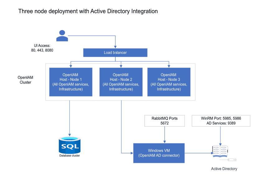
As indicated above, there are several deployment options when considering an HA configuration. A common high availability configuration used in mid-sized customers is the three-node cluster. Three-node clusters are a popular choice for HA configurations due to the performance and scalability benefits. For example, in the event of a node failure in a two-node cluster, the burden would shift to only one server which could potentially spike resource utilization on that node and throttle performance. Alternatively, during a server failure in a three-node cluster the burden would be split between the two remaining nodes and thus the stress on each server is diminished comparatively.
In this type of deployment, all of the OpenIAM services and infrastructure are replicated on each of the three Linux hosts that make up the cluster. The database is external to these servers and can have its own cluster.
If integration to Active Directory or another Microsoft application is required, then a Windows VM should be used to host the connector. In this example, we use the Active Directory PowerShell connector.
Note: This diagram is limited to integration with one application using common ports. The list of ports can change if integration with other applications is required.
N-tier configuration
Some OpenIAM customers have large user populations that require greater capacity than is possible with a three-node cluster. Other customers have a need to expose the UI layer externally. These organizations thus opted for an n-tier HA configuration. One example of an n-tier deployment is shown below where there are 4 layers and each layer has a three-node cluster.
- rProxy
- OpenIAM services + UI
- RabbitMQ
- Infrastructure services such as Vault, Redis, etc.
User requests sent to the platform are distributed across the three UI nodes using an external load balancer. Within the platform, HAProxy is used to distribute the load across the components. HAProxy allows us to detect if an instance of a component is down and then distribute the load to the components that are available. When a service has been restored, HAProxy will resume sending traffic to all available components.
Hardware/VM requirements
For a three-cluster deployment, please ensure each VM meets the minimum requirements listed below:
- OS: CentOS 8 Stream/RHEL 8.7
- Storage: 100GB
- RAM: 64GB
- CPU (vCPU): 10 vCPUs
Installing OpenIAM in a three-node cluster
This section describes how to deploy OpenIAM in a three-node server cluster. Shell scripts are provided by OpenIAM to automate the installation for HA configurations.
Prior to installation
- Switch to the root account in a terminal window.
sudo -i
- Install Git on the node that will be used to configure and install OpenIAM on all three nodes. For the remainder of this section, we will refer to this node as the installation node.
dnf install git -y
- Generate SSH keys on the installation node. Select Enter for each question prompted by the terminal.
ssh-keygen
- Next, propagate the public key to all of the nodes in the cluster. In the installation node terminal, enter the following commands and select Enter:
cat ~/.ssh/id_rsa.pub >> ~/.ssh/authorized_keyscat ~/.ssh/id_rsa.pub
Copy the output from the above commands. SSH into the other two nodes and execute the following command:
echo "Value from the buffer" >> ~/.ssh/authorized_keys
For example:
echo "ssh-rsa AAAAB3NzaC1yc2EAAAADAQABAAABAQDKcniMIHk8xwrR5lMQjCGS1fQSqJoOv1vStYORTW8ni7HS4diPtAEFbHMe/uYyIowMzwo6nBI7bzxyzwAPwSiuxQ7Qrv/FdNChS2sBT2pQVMHow81YA31XN6gutGQNVBMMCGe2FeVgPB8+GKvWIM9hxHCCVIfg/s/xNV7HFGJhd+mVIQZuN2OfMbfmJ1l11IhsKhgoF6OY6AzEOuesIY+sBnEIaRbUT12tBrqKIPwLgyeLH5fnp31sBmY637nCjc4pN4tQsiTdaxDuR4Q5Ynp2iF37NFuOBvCAOKfSDGX8gcN/uxqI24se5BpGSISizWLE+sFUstHgQFdbKsCtgMsv node1" >> ~/.ssh/authorized_keys
- Clone the openiam-cluster-rpm Git repository onto the installation node. This repository contains utilities to simplify the installation.
git clone git@bitbucket.org:openiam/openiam-cluster-rpm.gitcd openiam-cluster-rpm
Note: you may need to upload your SSH key to Bitbucket. Instructions for doing so can be found on this page: https://support.atlassian.com/bitbucket-cloud/docs/configure-ssh-and-two-step-verification/
Installation
- Update the file named infra.conf according to your infrastructure. Use VI or Nano to replace default values with the nodes’ names and IP addresses.
nano ./infra.conf
- Next, execute the installation script. This step will require internet access.
./install.sh
Installation may take several minutes to complete.
- Initialization will begin. Answer questions when prompted.
Starting/Stopping OpenIAM
The OpenIAM cluster will start automatically following initialization. In the event you may need to start or stop OpenIAM at a single node or for the entire cluster, please refer to the following commands:
- Starting OpenIAM components on a single node
openiam-cli start
- Stopping OpenIAM components on a single node
openiam-cli stop
- Starting OpenIAM on the entire cluster
cluster openiam-cli start
- Stopping OpenIAM on the entire cluster
cluster openiam-cli stop
Port configuration
| Host | Ports | Description |
|---|---|---|
| OpenIAM cluster nodes | The following ports should be opened on each node in the cluster. | |
| 443 | The primary port that will be used by end users after SSL has been enabled. | |
| 80 | The port that will be used by end users before SSL is enabled. | |
| 8080 | The port that allows use of OpenIAM without going through rProxy. Access to this port is helpful during development. | |
| 15672 | The RabbitMQ management interface. | |
| The following ports should be opened on each node in the cluster to support intercluster communication between stack components. | ||
| 22 | SSH | |
| 8000, 8001 | Cassandra | |
| 8182 | JanusGraph | |
| 7000, 7001, 7002 | Redis | |
| 9200, 9300 | Elasticsearch | |
| 5671-5672, 35672-35682, 4369 | RabbitMQ | |
| 2379 | Etcd (Vault DB) | |
| 2380 | Application cluster | |
| OpenIAM Linux host - Node 1 only | 8200 | Vault |
| 9080 | Service port | |
| Windows Connector VM | 5672 | The connector will send and receive messages back to RabbitMQ using this port. |
| 5985, 5986 | The WinRM ports used by the connector. | |
| 9389 | The port used to access Active Directory Web Services. |
Load balancer configuration
After installing the OpenIAM server cluster, load balancing must be configured. Load balancers are available in hardware-based and software-based solutions.
The hardware load balancer leverages algorithms to distribute requests to the nodes of the cluster to maintain performance and redistributes traffic in the event of a node failure. A particularly common algorithm is round robin which simply forwards requests to the next available server in turn. In the three-node cluster example above, requests are directed to an external load balancer which then routes traffic to the appropriate OpenIAM node based on current server resource utilization.
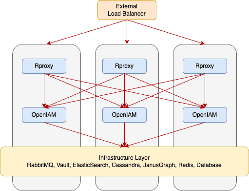
Load balancing can also be configured to take place at the component level as opposed to the node level using a software-based solution like HAProxy which is configured on every node. For example, if the Redis or ElasticSearch component in node 1 fails, the request can be forwarded by HAProxy to the same component in node 2.
An example topology displaying load balancing at the component level in a three-node cluster is shown below.

